
No.7 "How thin the thermoelectric module could be?"
The shape of a bismuth telluride thermoelectric module is basically plate-like and its thickness, or height, is 2 to 5 mm. If we need far less thickness, is it possible to decrease the thickness to one micrometer? It's interesting to think about what could happen?
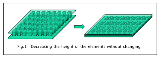
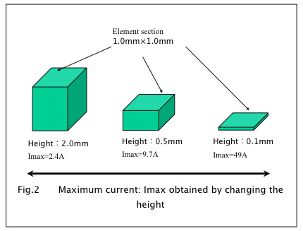
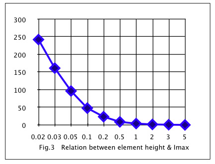
The lower the element height, the bigger the maximum current, Imax.
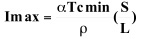
When we make the element height lower and lower, while keeping the element section unchanged as shown in Fig 1 and Fig2, the maximum current of the element get larger and larger in an exponential manner as shown in Fig3. If we set the bismuth telluride element section 1×1mm, maximum current of 2.4A(element height:2.0mm) increases to 9.7A(element height:0.5mm) and even to 49A(element height:0.1mm)!. This is because the maximum current, Imax, is expressed as the following equation where Seebeck coefficient α, resistivityƒÏ, section area S, length L and the minimum temperature at the cold side Tcmin are defined for the element couple.(I calculated the figures using α=400µV/Kelvin, ƒÏ=1000µƒ¶cm, Tcmin=-39°C=234Kelvin, which means ΔTmax at Th=27°C is 66°C.
Do you have any problem when you have a big current? Yes, you have to have thick leads, and you may have joule heat problem for copper electrode and solder. The joule heat is not an only problem, but you should know more critical issue, the influence of "Thermal Resistance" the author wrote in the No.6 Story. As far as we use a thermoelectric module to get a big temperature difference, we have to apply a nearly maximum current of the element, eventually the dissipating heat Qh become larger with the increasing Imax value as indicated in the following equation.
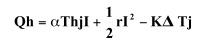
Where, Thj is hot-side junction temperature, I is current, r is element electrical resistance, K is element thermal conductance andΔTj is junction temperature difference.
Copper electrode, solder, NiP plating and ceramic plate, except element, are all "undesired thermal resistances". These thermal resistances(=R) make temperature difference loss of (R×Qh) when the pumping heat is zero, eventually decreasing the maximum temperature difference(=ΔTmax) in addition to joule heat.
The lower the element height, the smaller the maximum temperature difference.
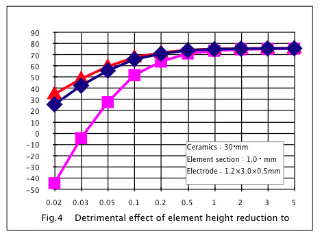
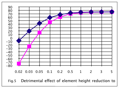
Let us calculate how the electrical and thermal resistance affect on the maximum temperature difference; ΔTmax. Materials constants used in the calculation are shown in Table1. Fig4 shows the separated effects of electrical resistance and thermal resistance on the ΔTmax to the height of the element. Where electrical and thermal resistances of copper electrode, solder, NiP plating and ceramics, alumina or aluminum nitride, are included. From Fig4, though the effect of electrical resistance is not so large to the thickness of 0.2mm element height, you can find a significant effect at the height of 0.1mm. The effect of thermal resistance of alumina ceramics is obvious at the element height lower than 0.3mm, while the effect of thermal resistance of aluminum nitride ceramics is not so large to 0.2mm element height. With alumina ceramic plate, you can get ΔTmax of only 28°C at 0.05mm thick, while with aluminum nitride ceramic plate, you can get 57°C at the same thickness. This shows a very serious effect of thermal resistance of the insulation plate for a thermoelectric module. Fig5 shows the effect of element height to theΔTmax with the loss from total electrical and thermal resistances. From Fig5, when you just lower the height of the element, while keeping the element section the same, the element height limit or minimum height, to obtain temperature difference of 60°C, seems 0.2mm for alumina or 0.1mm for aluminum nitride respectively.
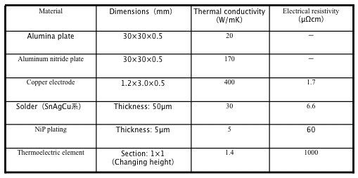
Table 1 Material parameters used in the
With the condition in Table 1, how much maximum current would be a limit to get ΔT of 60°C?
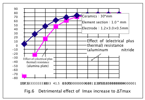
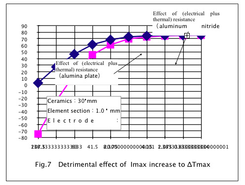
When you put the element height lower and lower, the Imax becomes higher and higher. Then, with the condition in Table 1, we have to see the graph showing the relation betweenΔTmax and Imax. Fig6 shows this relation and it has a linear relationship. Fig7 shows the same relationship with the logarithmic horizontal axis. Fig7 better expresses the effect of increasing Imax. From this graph, we can see the upper limit of Imax to be able to get ΔTmax of 60°C seems 20A for alumina or 40A for aluminum nitride. From this fact, a high heat conducting material is very effective to the enhancement of heat dissipation density.
The very similar results ? ----------- of the story as No.6
In order to make the structure of a thermoelectric module, you have to use copper electrode, solder, NiP plating and ceramic plate. But these materials are all electrically and thermally deteriorating factors for the performance of thermoelectric element itself. The magnitude of deterioration increases in proportional to the heat dissipation density, or heat dissipated at a unit area, at the hot side of a thermoelectric module. From this reason, you can guess there is a limit to thinning or downsizing of thermoelectric module.
Note: The limit of the element height and the maximum current values could be different from these results when you use different calculation basis.
Written by Y. Kibayashi