
The last story "Application of TEC for electronic devices: Why should they be cooled? "
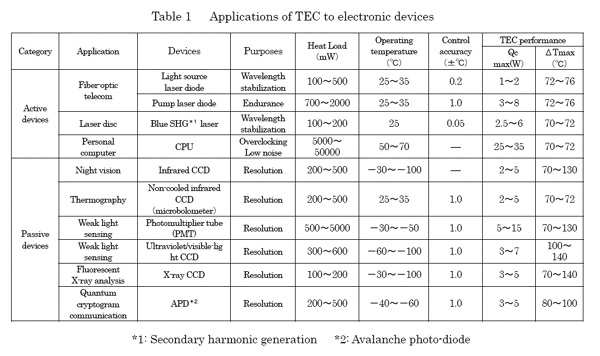
The most suitable application of thermoelectric cooler(TEC) must be those to electronic devices. TEC is most convenient to cool a small area. The table 1 shows applications to electronic devices. One of a very popular use of TEC, such as " I have heard of one ! " may be cooling of CPU in personal computer. But, should we say things about electronic devices, TECs are mostly used for fiber-optic telecommunication.
The other applications for electronic devices are unpopular for most people, however, people interested in astronomical observation should know that TEC is often used in taking photographs of stars with CCD camera. And, in Iraq and Afghanistan, infrared CCD cameras installed in unmanned aircraft played a significant role at night surveillance. In this case, TEC was used to cool infrared CCD to detect exhaust heat from combat vehicles.
In a little bit unpopular application, when high performance blue-laser disc by SHG(secondary harmonic generation) had been planned, TEC had drawn a lot of attention to cool SHG devices. We expected a significant business with this application, but, as you know, room-temperature-operational blue laser was invented by Shuji Nakamura, so, cooling became unnecessary now.
A more unpopular application is to cool X-ray CCD in element analysis by fluorescent X-ray. A futuristic TEC application may be one to cool receiver for Internet cryptograph communication. This is called "quantum cryptograph communication", and it is a very perfect, wire-tapping-preventive, communication measure. Because, very weak light; signal by single photons, is used in this method, it is inevitable to cool receiver to enhance the sensitivity.
This time, I will explain why TECs are used in these devices and what role TECs are playing. That means what phenomena are occurring in cooling electronic devices. Let me start the story.
1.Cooling of laser diode for fiber-optic telecommunication
Lasers used in fiber-optic telecommunication are semiconductor, called laser diodes.
These lasers are mainly categorized to light source(transmitter) laser and pump(amplifier) laser. The lights emitted from a light source are infra-reds which have two kind of wavelength, 1310nm(nanometer:one billionth of a meter) and 1550nm. Activefiber-optic networks construction and today's Internet popularity have come after 1995. Then, EDFA(Erbium Doped Fiber Amplifier: Amplifier by pump laser. In a optical fiber, it is necessary to amplify signal light to be able to transmit more than several hundred kilometers.) was put into practical use in 1995 along with WDM(Wavelength Division Multiplexing) technology, which enabled a high-speed, low cost communication system in which dozens of wavelength were transmitted in a single fiber and these light signals were amplified by EDFA at the same time.
Until then, a light source laser could be attached to single optical fiber, and transmitting speed was only 622Mb/s(megabit per second: 622-million signal in a second) which was very slow compared to today. From this reason, number of TECs to control laser diode temperature were very small.
After WDM had been adopted, number of light source lasers has gradually increased. Supported by heavy demand of Internet and other communication, which requires high speed 10Gb/s(gigabit per second: 10-billion signal in a second), DWDM (Dense WDM) which uses over one hundred of light sources, has become popular. In this system, TECs to control laser temperature both for light sources and pumps were surprisingly inflated. With increasing number of wavelength, high-power pump laser cooled by TEC has been required to amplify many wavelength signal by EDFA. And, for ultra-long haul lines, RAMAN pump laser, also equipped with TEC, has been developed.
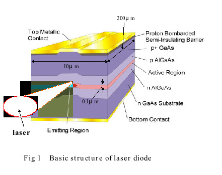
The basic structure of laser diode is shown in Fig 1, and you can see very narrow emitting part of laser light. So, the current density in the laser emitted area, called active layer, amount to such huge figures as several hundred to several thousand amperes per one square centimeter. The efficiency to be able to convert charged electric power to laser light is 15 to 30%, so the rest becomes heat. In addition, thermal conductivity of the diode is not so large, the diode crystal will immediately melt down if the heat will not be diffused into highly heat conductive materials such as diamond and silicon carbide.
In the meantime, the wavelength emitted from laser diode changes with temperature. (See Fig 2). The graph shows a linear relation in which wavelength increases 3nm in every 10°C(0.3nm in every 1°C). This indicates that the length of laser diode crystal expanded with increasing temperature, which elongated laser resonator length(edge to edge distance of the crystal), resulting in longer wavelength.
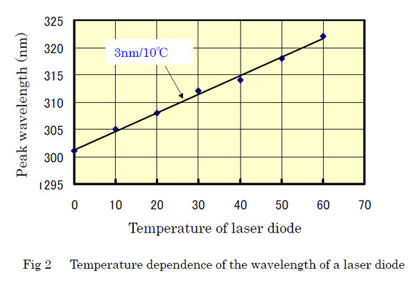
The neighboring wave distance of many waves in DWDM, e.g. in the case of C-band, in which there are 100 wavelength in 30nm width, is 0.3nm. So, if the temperature changes one degree, the neighboring waves overlap each other. So, light source laser temperature should be controlled to ±0.2°C. A kind of WDM called CWDM(Coarse WDM) are employed as one solution for medium/short distance. This system uses neighboring distance of 20nm, only four waves in a fiber, which needs no TEC.
Pump lasers(980nm and 1480nm) used for light amplification need not have a strict temperature control of laser diode compared to light source lasers, but the power is about ten times higher than the latter. This big power makes it hard to keep diodes at room temperature without active cooling by TEC, unless otherwise, laser diodes' life becomes very short.
Note: What is the definition of laser diode's life? Laser diode's life is basically defined as an increased percentage of the operational current. But for MQW(Multi Quantum Well) laser used in WDM, life is defined as a changed increment of the peak wavelength. For example, a laser for fiber-optic telecommunication has a life of several million hours at 25°C, at 50% increase of operational current, under the constant emission. And, also it has a life of several hundred thousand hours at 25°C, at 0.2nm wavelength change, at the same emission. So you can understand a sufficient life of this laser diode for telecommunication.
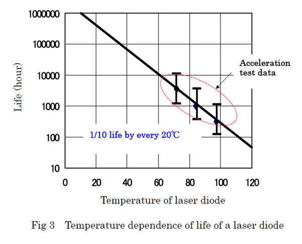
Fig 3 shows a relation between temperature and life of laser diode as an example. From this graph, you can read that laser diode's life sinks to one tenth in every 20°C increase of temperature. For this reason, laser diode's temperature is controlled at 25 to 35°C.
In conclusion, the role of TECs cooling laser diodes in fiber-optic telecommunication is to control crystal dimension of diodes(in the case of light source laser) and temperature(in the case of pump laser) to assure reliable and long-lasting communication system..
2.Cooling of blue-SHG laser for laser discs
Today, blue lasers which can operate for over ten thousand hours at room temperature without TEC cooling have already been developed by Nichia and so on, and commercialization of recorder/player such as HD-DVD and Blue-ray Disc, two-hour-recordable of high definition TV image, are in reality.
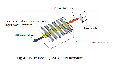
But, ten years ago, many blue-SHG(Secondary Harmonic Generation) lasers had been developing in a lot of firms and institutions, using special SHG crystals or lightwave circuits capable of halving high power infrared laser diode's light into blue(See Fig 4). For SHG, it is commonly necessary to strictly control the temperature of the SHG crystal to halve the incident wavelength. TEC is inevitable to control it to 0.01 to 0.05°C accuracy to keep the wavelength of blue emission. Also in this case, to control the crystal temperature means to "keep the length of the crystal constant".
High power green and blue lasers are still considered to apply SHG device in the future with TEC cooling.
3.Cooling of CPU
As you know well, CPU(Central Processing Unit) in your personal computer cannot show you the catalogue performance without any kind of cooling. This is because the power consumption became huge with increasing transistor density in a CPU chip to enhance calculation speed in accordance with Moor's Law. This resulted in big heat dissipation from CPU.
Fig 5 shows a real measurement of a relation between CPU performance and temperature, and the axis of abscissas show passing time. You can see CPU performance downs to half when temperature rises 15°C. By seeing this, please do not think "I can get better performance by cooling CPU, because temperature rise will harm the performance". The slowing speed of CPU came from the reason that temperature control function worked to down the clocking speed, to avoid CPU failure. If you want to enhance the performance of a CPU, you have to cool it and you have to set the clocking speed faster(over-clocking) than catalogue value at the same time.
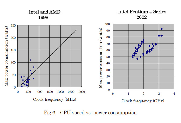
Upper surface temperature limit is specified to 70-100°C in design, so that the performance does not degrade at least to these design temperatures. Highest limit temperature of silicon semiconductor making CPU is around 150°C, so if you overheat beyond this temperature, functions as semiconductor should be lost. Cooling CPU is inevitable to keep the performance, but TEC increases power consumption and cost, and also pose a condensation problem. From these reasons, TEC is not used in the current market. Instead, popular CPU cooling is made by metal heat-sink with electric fan. Fig 6 is a comparison of CPUs between 1998 and 2002, and you can find that recent CPUs have less power consumption, in spite of their higher speed, compared to several years ago.
But, very recent high performance CPUs with heat dissipation of such a big 100watts, the rotation speed of electric fan becomes very high, which creates significant noise. So, again, people have begun to consider a combination of TEC or radiator with low-speed fan to be able to suppress noise.
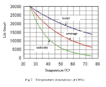
Meanwhile, semiconductor products have some amount of quality width, and you can read from Fig 7 that this lucky to unlucky width gives a very large life difference. For example, if you buy an unlucky one, and use it 8 hours a day for 365 days, you may have failure within two years! I bet cooling is still a big thing for CPU even without TEC.
Above mentioned electronic devices as laser diode and CPU are categorized to "Active devices", because they dissipate heat by themselves. (As for SHG, it includes laser diode in it's system.)
Next, I will explain about "Passive devices" which do not dissipate heat by themselves. All of these devices are light sensors, or photon detectors for infrared, visible, ultraviolet and X-ray. Please note that light sensors have signal processing circuit which dissipates small amount of heat.
4.Cooling of infrared sensor
In recent days, infrared CCD cameras to detect infrared rays as an image, are widely used. So, I will explain about it. Infrared CCDs cooled with TEC are sorted into "Infrared CCD" and "Uncooled infrared CCD". Infrared ray having wavelength of 8-14µm(micrometer: one thousandth of a millimeter ) is emitted from low temperature objects, including humans and animals, at not so higher temperature above room temperature. In order to take clear and distinctive images of these creatures from the background, infrared CCD cameras are commonly used.
Infrared CCDs are made from exotic crystals such as PtSi(platinum silicon), InSb(indium antimony) and HgCdTe(mercury cadmium tellurium). Although these crystals have high sensitivity for infrared rays, it is necessary to cool CCD chip down to -150°C with liquid nitrogen or Sterling cooler to obtain a clear image. If not cooled, these sensors have a big noise(dark current), and lose it's function as a detector.
Today's minimum cooling temperature of multi-stage TEC is around -100°C, so TEC cannot cool these CCDs for 8-14µm infrared. Infrared sensors in Table 1 are those to detect 3-5µm infrared rays(mainly emitted from 300-500°C object like engine exhaust gas). These CCDs are made from PbS(lead sulfide) or HgCdTe(different composition from above) crystal and cooled with multi-stage TEC to -30 to -100°C.
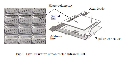
Meanwhile, "Uncooled infrared CCD", which detection principle is totally different from conventional infrared sensors, can detect 8-14µm wavelength in an "uncooled" condition. This sensor's CCD consists of several hundred thousand of 30-50µm square small heat detecting plates, called microbolometer. This is a kind of MEMS(Micro Electro-Mechanical System) and each detecting plate connects to silicon circuit to make CCD(See Fig 8). The intensity of infrared rays is measured by measuring resistance changes in each detecting plates. Even if it is called "uncooled", uncooled infrared sensors are often equipped with single-stage TEC, which controls CCD to around room temperature. When CCD temperature is higher than ambient or temperature distribution over TEC is not flat, it cannot clearly detect human or animal. In recent years, uncooled infrared cameras have become very popular.
5.Cooling of photo-multiplying tube(PMT)
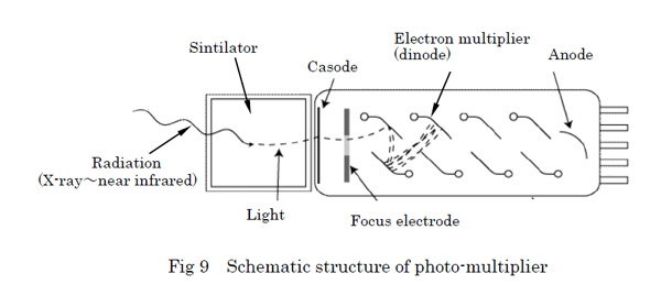
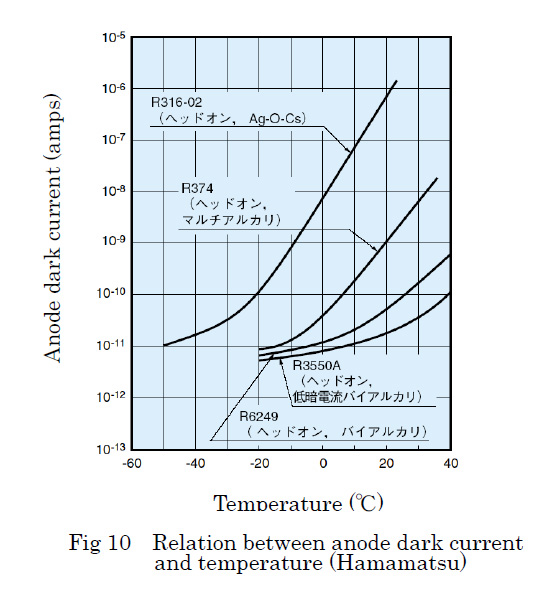
Even very weak light can be observed by amplification with PMT. The structure of PMT is schematically illustrated in Fig 9. When weak incident light comes into cathode, it create free electrons which are amplified to ten million times by amplifier electrodes(dinodes) to be able to detect. The amplification is so large that it has ultra high sensitivity to be able to detect a single photon, and is widely applied to spectroscopy, astronomy, medical treatment, biotechnology, semiconductor manufacturing, material development and so on. However, noise(anode dark current) increases with the increasing temperature of cathode and dinodes(see Fig 10), PMT is often used with TEC cooling at cathode or cooling of whole PMT to around -30°C.
6.Cooling of silicon CCD
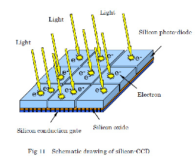
A silicon CCD(Charge Coupled Device) is installed in your Digital camera. Silicon CCD is a kind of LSI(Large Scale Integration of semiconductor circuits) to record/display images, made from a combination of silicon PN junction photo-diodes(light sensor) and CCD circuit(see Fig 11).
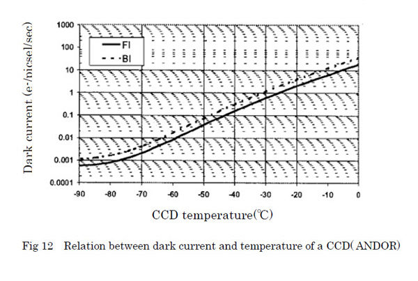
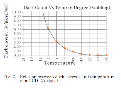
Application of silicon CCD to be cooled with TEC is mainly to taking pictures of celestial bodies. In order to take pictures of distant stars, tens of millions or hundred of millions far away, emitting very weak light, it is necessary to have a long exposure: 5-10 minutes. This long time exposure also collects a lot of noise, and CCD have to be cooled so noise(dark current) of CCD is minimized. You may have noticed that ordinary digital camera make very "coarse images" when taken at night by exposing tens of second without flashlight. This noise of CCD comes from thermal effect at silicon PN junctions of the CCD which is explained by carriers(electrons and holes) created by Seebeck Effect. Fig 12 and Fig 13 shows relation between dark current and temperature of typical CCD. From these graphs, you can see that noise of CCD can be dramatically reduced when cooled to subzero temperature. Generally speaking, dark current doubles when temperature rises 6 to 10 degree C. As for high-sensitivity camera, CCD is commonly cooled down to -50-60°C, and some products can cool down to -100°C.
You have to note that CCD's pixels(image unit) have different performance among them. To get a right image by compensating this difference, it is necessary for each CCD to do "Dark Correction: correction with closed shutter" and "Flat Correction: correction at white image".
Silicon CCD can take images from X-ray to visible light. Astronomical observation by X-ray may be best known for X-ray observation satellite "Asuka", in which X-ray CCD is cooled down to -70°C with multistage TEC. And, in X-ray spectrometer for micro-X-ray analysis, multi-stage TEC is working as well.
7.Cooling of APD(Avalanche Photo-Diode)
APD is a very high sensitivity photo-diode, and it has been used for telecom receiver and for many kind of photo-spectroscopy. In these applications, TEC cooling to minimize dark current was not necessary in almost cases.
But in "quantum cryptograph communication", light particle(photon) is used to transmit signals, and it is inevitable to cool APD receiver with multi-stage TEC and reduce dark count("dark current" is called "dark count" because photon is counted one by one).
And, different from other devices, we have a problem to cool APD. It is not appropriate for APD to cool down to the temperature as low as possible. Because, a phenomenon called "after pulse" occurs, and this is more apparent at lower temperature. Some of the electrons avalanche-amplified are trapped by dopant(small amount of additive element in semiconductor) and then this trapped electrons avalanche-amplified to give a error signal; an obstacle for APD to operate in high speed. It is a dilemma between "minimum dark count" and "minimum after pulse". The conclusion is that it may be appropriate to cool down around to -50°C. Yes, this is a comfortable temperature for multi-stage TEC.
This time, I have written a little bit theoretically about "cooling mechanism" in electronic devices when cooled with TEC. If you could find any explanations like " I didn't know! ", this story would be a great success.
060730 Yasutada Kibayashi